Senin, 26 September 2011

Lecture 1B.3: Background to Loadings


ESDEP WG 1B
STEEL CONSTRUCTION:
INTRODUCTION TO DESIGN

Lecture 1B.3: Background to Loadings

OBJECTIVE/SCOPE:

To provide an introduction to the sources of loads on structures and how loads can be quantified for the purpose of structural design.

RELATED LECTURES:

Lecture 1B.2.1: Design Philosophies

SUMMARY:

Various types of loads (dead, imposed and environmental) and their classification as permanent, transient or accidental within Eurocode 1: Basis of Design and Actions on Structures, is considered. Calculations for dead loads on the basis of material densities and component sizes are explained. Means of estimating imposed loads based upon usage and the implications of change of use are discussed. Loads due to snow, temperature and seismic effects are considered briefly. The statistical treatment of wind and wave loads, and their dependence upon wind speed and wave height respectively, are described. The importance of load characteristics, other than simply their magnitude, is considered. These characteristics include fatigue, dynamic and aerodynamic effects. Simplified treatments for dynamic loads are described.

1. INTRODUCTION

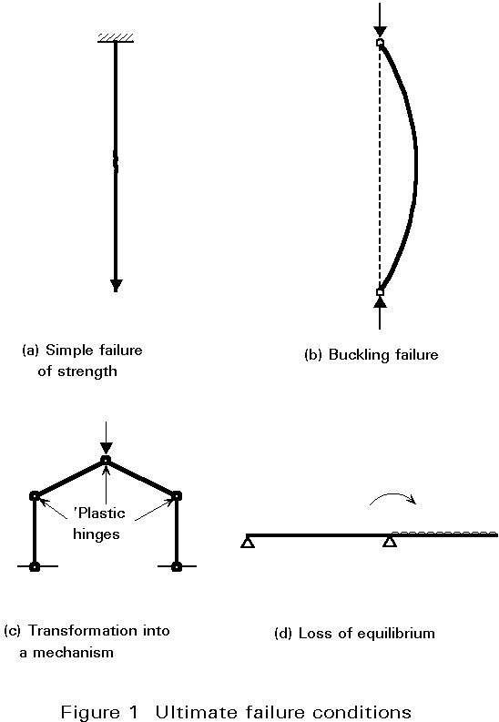
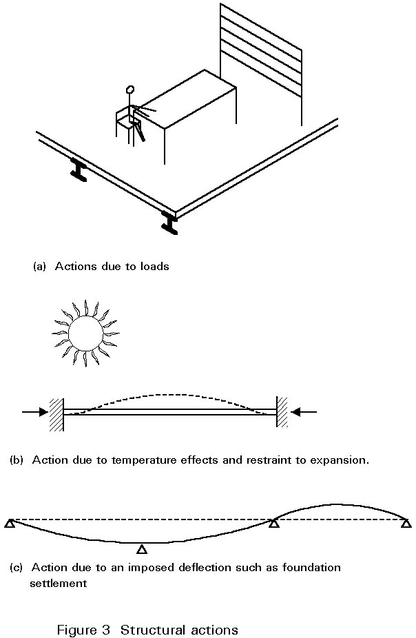
Structures are subject directly to loads from various sources. These loads are referred to as direct actions and include gravity and environmental effects, such as wind and snow. In addition deformations may be imposed on a structure, for instance due to settlement or thermal expansion. These 'loads' are indirect actions. In applying any quantitative approach to structural analysis, the magnitudes of the actions need to be identified. Furthermore, if the structure is to perform satisfactorily throughout its design life, the nature of the loads should be understood and appropriate measures taken to avoid problems of, for instance, fatigue or vibration.
The magnitude of loads cannot be determined precisely. In some cases, for instance in considering loads due to the self-weight of the structure, it might be thought that values can be calculated fairly accurately. In other cases, such as wind loads, it is only possible to estimate likely levels of load. The estimate can be based on observation of previous conditions and applying a probabilistic approach to predict maximum effects which might occur within the design life of the structure. (In fact, the extensive wind records which are now available mean that wind loads can often be predicted with greater accuracy than self-weight). Loads associated with the use of the structure can only be estimated based on the nature of usage. Insufficient data is available in most cases for a fully statistical approach and nominal values are therefore assigned. In addition, problems of change of use and fashion can occur.
In analysing structures it is rare to consider all loadings acting simultaneously. This approach may be because the most severe condition for parts of the structure occurs when some other combination of load is considered. Alternatively it may be that the possibility of such a condition actually occurring is extremely small. However, the risk of coexistence of apparently unrelated loads may be greater than is first imagined. Correlations can be produced from unexpected sources or from coincidences which, although physically unconnected, are temporarily connected. For example, floor and wind loads would normally be considered as unrelated. However, in hurricane areas residents on the coast might be expected to move their ground floor contents to upper floors if a hurricane warning, with associated tidal surge, were given. This circumstance could very easily produce extreme floor loads in combination with extreme wind loads. This case may be a very special one but there are others. The risk of fire may not be considered correlated with high wind loads, yet in many parts of the world high winds are more likely in winter, which is also the period of greatest fire risk.
For these reasons it is convenient to consider loads under various categories. The categories can then be ascribed different safety factors and applied in various combinations as required. Traditionally, loadings have been classified as dead, superimposed and environmental loads. These classes include a wide range of gravity effects, seismic action, pressures due to retained material or liquids, temperature induced movement, and, for marine structures, water movement. The Eurocodes on actions and steelwork design [1, 2] classify loads and other actions as permanent, variable and accidental. These classes of action will be considered in more detail in the following Sections.
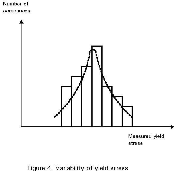
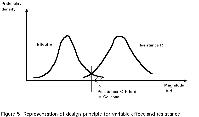
In limit state design, characteristic values of actions are used as the basis of all calculations. They are values which statistically have only a small probability of being exceeded during the life of the structure. To provide a margin of safety, particularly against collapse, partial safety factors are applied to these characteristic values to obtain design quantities. In principle, different partial safety factors can be applied depending on the degree of uncertainty or variability of a particular type of action. In practice, whilst this appears to be the case, the actual values of partial safety factors used incorporate significant elements of the global safety factor and do not represent a rigorous probabilistic treatment of the uncertainties of the actions.

2. PERMANENT ACTIONS

Permanent actions, as the name implies, are always present and must be considered in all cases. They comprise what are traditionally referred to as dead loads, but may also include permanent imposed loads due, for instance, to machinery or stored material.

2.1 Dead Loads

Dead loads are gravity loads due to the self weight of the structure and any fixtures or finishes attached to it (Figure 1). Their magnitudes can be estimated with reasonable confidence based on prescribed dimensions and a knowledge of material density. Even so, variations due to constructional tolerances and natural variations in materials, will exist. Furthermore, fixtures, fittings and finishes may be replaced or modified during the life of the structure. This possibility has been recognised in calculating loads on bridge decks, for which a separate load category of 'superimposed dead load' is included to allow for surfacing which is likely to be replaced a number of times during the life of the bridge. For this situation there is consequently a much greater potential for variability than for other dead loads.
A similar condition exists within certain types of building with respect to partitions (Figure 2). Where the position of walls is predetermined their weight can simply be included as a dead load. For more speculative development, internal partitions will be the responsibility of the client and their layout is likely to change many times during the life of the building. An allowance, as an equivalent uniformly distributed load, is therefore normally made.
Schedules of densities for common building materials are listed in Eurocode 1 [1] and manufacturers of proprietary products, such as cladding, blockwork, raised floors, etc. provide information on weights. Together with specified dimensions, these data enable dead loads to be calculated. Where dead loads are not strictly evenly distributed over a plan area, such as timber floor joists located at discrete intervals, they are often represented as an equivalent uniformly distributed load for convenience in design calculations. As long as the equivalent magnitude is determined in a rational manner, any differences between this simplified approach and a more rigorous analysis taking account of the actual location of the joists will be negligible.
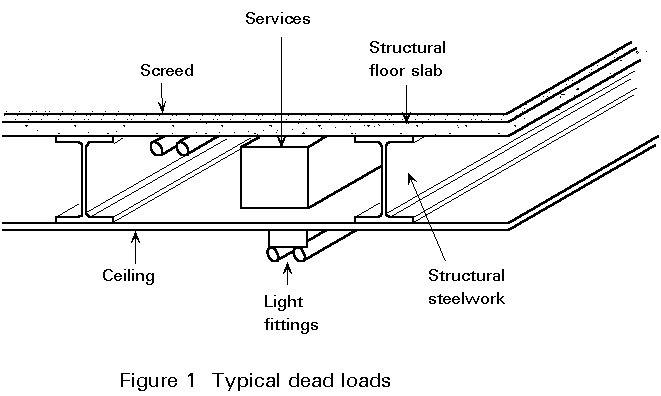
To determine dead loads, consider, for example, the case of a floor consisting of a 150mm thick reinforced concrete slab with 50mm lightweight screed and a 15mm plaster soffit. Details are shown in Figure 3 together with densities for each material. The total dead load per square metre of floor plan can be calculated as follows:
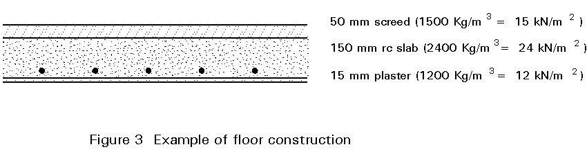
lightweight screed 15 x 0,05 = 0,75 kN/m2
rc slab 24 x 0,15 = 3,60
plaster 12 x 0,015 = 0,18
total dead load = 4,53 kN/m2
In addition an allowance would normally be made for any services or fittings (electric lighting, pipework, etc.) fitted to the underside of the slab or located within the screed or under a raised floor (Figure 4). This case is another where an equivalent uniformly distributed load is used to represent load sources distributed in an uneven manner. A value between 0,1 and 0,3 kN/m2 is normally adequate to cover such installations.
The weight of walls can be treated in a similar manner to floors by considering the various component parts and summing the weights per square metre on elevation. For example, consider a cavity wall consisting of a tile-hung brick outer leaf (100mm thick) and a plastered blockwork inner leaf (150mm thick) as shown in cross-section in Figure 5.
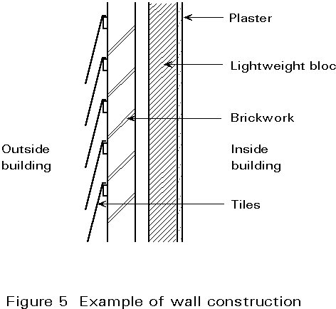
The total dead load is determined as follows:
tiles 0,6 kN/m2
brickwork 2,1
blockwork 1,4
plaster 0,2
total dead load of wall 4,3 kN/m2
By multiplying this value by the height of the wall, the load intensity as a line load on the supporting structure can be determined.
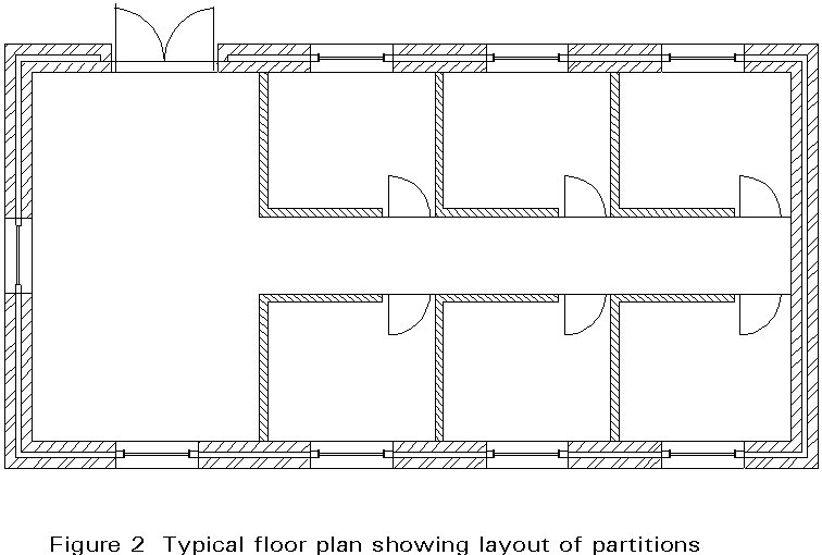
Loads due to internal lightweight stud or blockwork partitions cannot normally be treated in such a rigorous manner since their location is often not known at the design stage and in any case may change during the life of the building. Instead an allowance is made within the assessment of imposed loads which is described under variable actions.

3. VARIABLE ACTIONS

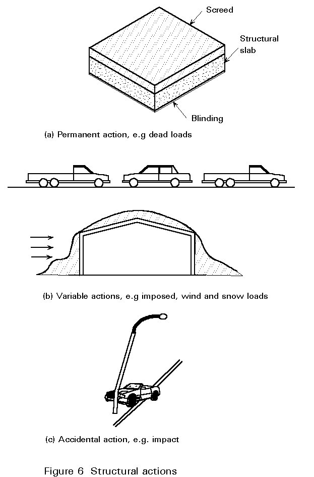
Variable actions comprise loads which are not always acting but may exist at various times during the normal use of the structure. They include loads due to the occupation of a building and traffic on bridges (imposed loads), snow and wind loads (environmental loads), and temperature effects (Figure 6). They do not include accidental conditions such as fire, explosion or impact.
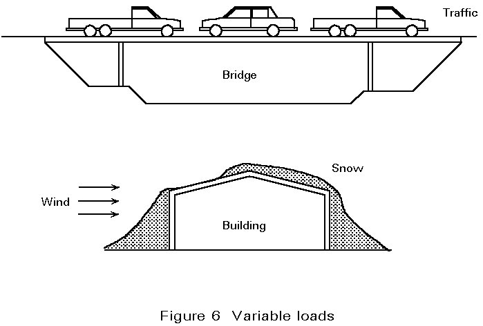
3.1 Imposed Loads

Imposed loads - sometimes referred to as "superimposed", "super" or "live" loads - are those loads due directly to the use of the structure. For buildings, they are concerned with the occupancy by people, furniture, equipment, etc. For bridges they are due to traffic, whether pedestrian or vehicular.
Clearly these conditions will be almost constantly changing and are rather more difficult to quantify than dead loads. For buildings, the approach has therefore been to relate imposed load levels to occupancy, and to base them on observation and sensible deduction. Eurocode 1: Basis of Design and Actions on Structures [1] distinguishes between four classes of loaded floor area as follows:
  • areas of dwellings, offices, etc.
  • garage and traffic areas.
  • areas for storage, production machinery and filing.
  • areas serving as escape routes.
The first class is further subdivided into four categories according to their specific use. They are residential (including hospital wards, hotel bedrooms etc.), public premises (such as offices, hotels, hospitals, schools, leisure centres etc.), public premises susceptible to overcrowding (including assembly halls, conference rooms, theatres, shopping areas and exhibition rooms), and public premises susceptible to overcrowding and accumulation of goods (including areas in warehouses and department stores).
The characteristic values of the imposed loads for these different categories are given in Table 1. Thus domestic residences attract a lower imposed load than office accommodation; areas of public assembly, where large numbers of people could gather at any one time, are prescribed a high superimposed load. Storage areas must be particularly carefully considered and Eurocode 1 includes details of densities for a range of stored materials. Some of these, such as steel strip, will generate high loads, but even apparently innocuous conditions, such as filing stores, can experience very high loading levels. Escape routes must be designed for relatively high imposed loads.
Although such loads are used in limit state design in a semi-probabilistic way and are referred to as characteristic values (implying a statistical basis for their derivation) little data is available. A proper statistical analysis is not therefore possible and values specified are nominal quantities. One study which was conducted into office accommodation in the UK [4] revealed a wide variation in actual load levels for similar building occupancies. In all cases the load levels measured were considerably less than the characteristic values specified for the structural design. However, this observation must be viewed with some caution since design must allow for extreme conditions, misuse and panic situations.
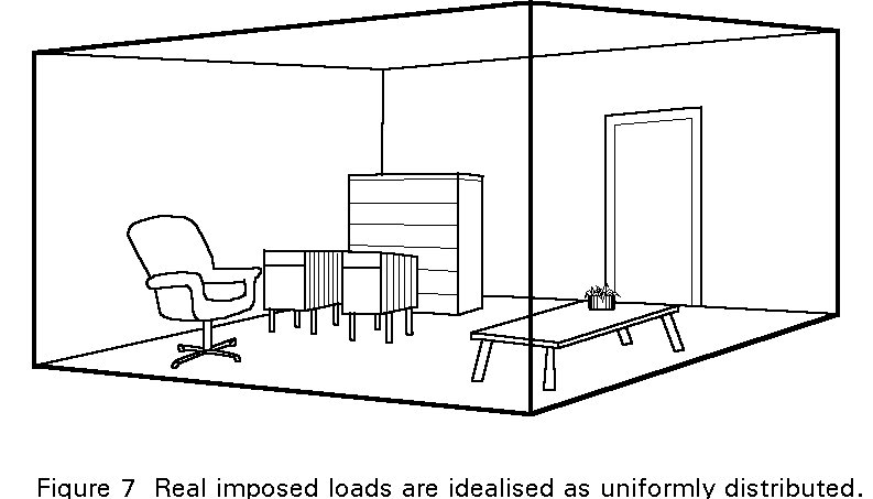
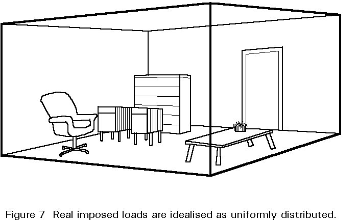
Note that, although imposed loading will rarely be evenly distributed, a uniform distribution of load intensity is normally assumed (Figure 7).

3.2 Permitted Reductions in Imposed Load

The nominal values of imposed load associated with different classifications of building occupancy and use represent extreme conditions. In many cases the probability of such conditions existing simultaneously throughout a building is remote. In recognition of this remote possibility some reductions in imposed load intensity may be permitted. Reduction applies particularly to columns in multi-storey buildings where it increases with the number of floors supported by a particular length of column. Typical reductions range from 10% to 30% and apply to imposed loads only. No reductions are permitted in dead load or for certain types of imposed load - notably in the case of storage areas, crane loads, and loads explicitly allowed for such as those due to machinery or due to people in public premises susceptible to overcrowding.

3.3 Superimposed Bridge Loads

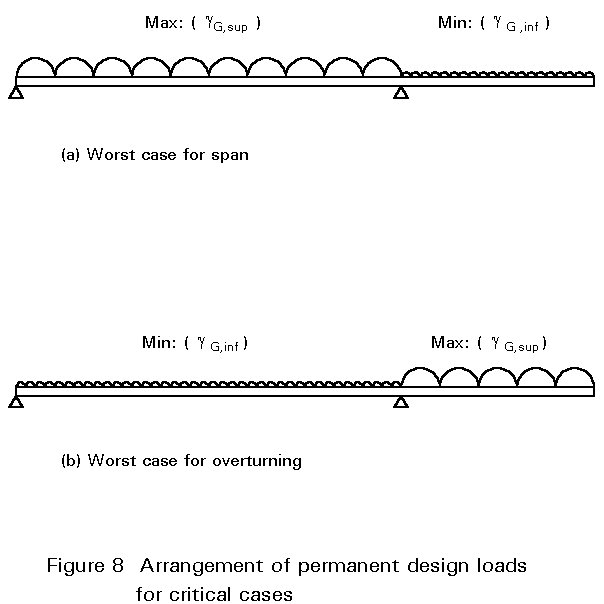
In practice a highway bridge is loaded in a very complex way by vehicles of varying sizes and groupings. In order to simplify the design process this real loading is typically simulated by two basic imposed loads - a uniformly distributed load and a knife edge load - representing an extreme condition of normal usage (Figure 8). The design is then checked for a further load arrangement representing the passage of an abnormal load. The magnitudes of all these loads are generally related to the road classification, the highway authority's requirements and the loaded length of the bridge.
For vehicular traffic within buildings, lightweight conditions (less than 16 tonnes) can be dealt with in categories such as cars, light vehicles and medium vehicles. For heavier traffic, highway loading must be considered.
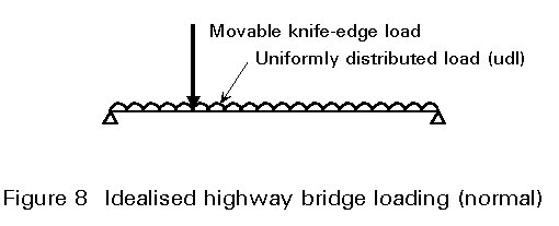
Railway bridge design must take account of static loading and forces associated with the movement of vehicles. As for highway bridges, two models of loading are specified for consideration as separate load cases. They represent ordinary traffic on mainline railways and, where appropriate, abnormal heavy loads. They are expressed as static loads due to stationary vehicles and are factored to allow for dynamic effects associated with train speeds up to 300km/h. Eurocode 1 also gives guidance on the distribution of loads and their effects and specifies horizontal forces due to vehicle motion. Centrifugal forces associated with the movement around curves, lateral forces due to oscillation of vehicles (nosing) and longitudinal forces due to traction and braking are included.
Other aspects of bridge loading which need to be considered include accidental loads and the possibility of premature failure due to fatigue under traffic loading.

3.4 Crane Loads

For buildings fitted with travelling overhead cranes, the loads due to the crane itself and the lifted load are considered separately. The self weight of the crane installation is generally readily available from the manufacturer, and the load lifted corresponds to the maximum lifting capacity of the crane. When a load is lifted from rest, there is an associated acceleration in the vertical direction. In the same way that gravity loads are equal to mass multiplied by the acceleration due to gravity, so the lifting movement causes an additional force. If the load is lifted very gently - that is with little acceleration - this force will be very small, but a sudden snatch, i.e. a rapid rate of acceleration, would result in a significant force. This force is of course in addition to the normal force due to gravity, and is generally allowed for by factoring the normal static crane loads.
Movements of the crane, both along the length and across the width of the building, are also associated with accelerations and retardations, this time in the horizontal plane. The associated horizontal forces must be taken into account in the design of the supporting structure. The magnitude of the forces will depend, as before, on the rates of acceleration. The normal procedure is to calculate the magnitudes on the basis of a proportion of the vertical wheel load.
The approach yields an equivalent static force which can be used in designing the structure for strength. However, the nature of crane loads must also be recognised. The possibility of premature failure due to fatigue under the cyclic loading conditions should be considered.

3.5 Environmental Loads

Environmental loads are clearly variable actions. For bridges and buildings the most important environmental loads are those due to snow and wind. For marine structures, particularly offshore installations such as oil platforms, loads due to water movements are often dominant. The action of waves generally represents the most severe condition. In certain geographical locations, the effects of earthquakes must be included in the structural analysis. All of these loads from environmental sources are beyond the control of man. It has therefore been recognised that a statistical approach must be adopted in order to quantify corresponding design loads.
The approach is based on the 'return period' which is a length of time to which recorded environmental data, such as wind speeds, snowfall or wave heights, is related. If records are only available over a relatively short period, data for the 'return period' may be predicted. The most severe condition on average over the return period then represents the design value. For a return period of 100 years, for example, it is referred to as the 1 in 100 year wind speed or wave height, etc. The return period normally corresponds to the design life of the structure. Clearly there is a degree of uncertainty about the process of predicting the most severe conditions likely to be encountered. Further simplifications are implicit in translating measured environmental data such as wind speeds or wave heights into loads.

3.6 Wind Loads

Wind forces fluctuate with time but for many structures the dynamic effect is small and the wind load can be treated using normal static methods. Such structures are defined as 'rigid' and Eurocode 1 [1] provides guidance on this classification. For slender structures the dynamic effect may be significant. Such structures are classified as 'flexible' structures and their dynamic behaviour must be taken into account.
The most important parameter in quantifying wind loads is the wind speed. The basis for design is the maximum wind speed (gust) predicted for the design life of the structure. Factors which influence its magnitude are:
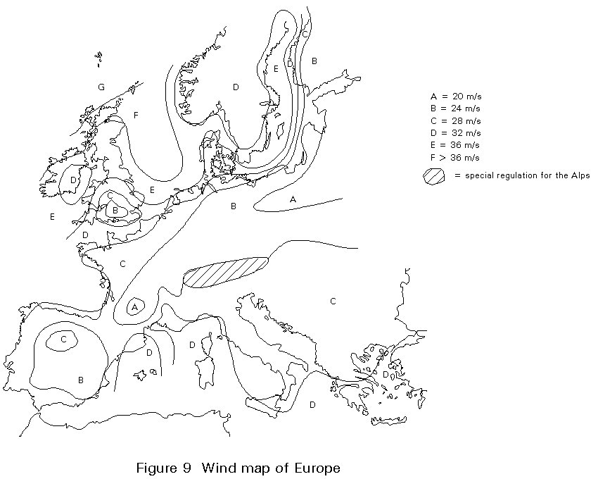
  • geographical location; wind speeds are statistically greater in certain regions than others. For many areas considerable statistical data is now available and basic wind speeds are published usually in the form of isopleths (Figure 9) which are lines of equal basic wind speed superimposed on a map. The basic wind speed is referred to in Eurocode 1 [1] as the reference wind speed and corresponds to the mean velocity at 10m above flat open country averaged over a period of 10 minutes with a return period of 50 years.
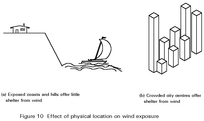
  • physical location; winds gust to higher speeds in exposed locations such as coasts than in more sheltered places such as city centres (Figure 10), because of varying surface roughness which reduces the wind speed at ground level. This variation is taken into account by a roughness coefficient which is related to the roughness of the terrain and the height above ground level.
  • topography; the particular features of a site in relation to hills or escarpments are taken into account by a topography coefficient.
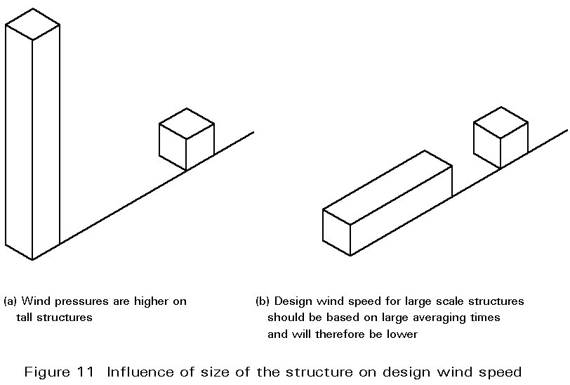
  • building dimensions; height is important in particular because wind speeds increase with height above ground level (Figure 11).
  • the mean wind velocity is determined by the reference wind velocity factored to account for the building height, ground roughness and topography. The wind pressure is proportional to the square of the mean wind speed. In addition the following parameters are important:
  • structural shape; it is important to recognise that wind loads are not simply a frontal pressure applied to the facade of a structure but are the result of a complex pressure distribution on all faces due to the movement of air around the whole structure. The distribution is further complicated by adjacent structures and natural obstructions/variations such as hills, valleys, woodland which may all influence the pattern of air movement and associated pressure distribution.
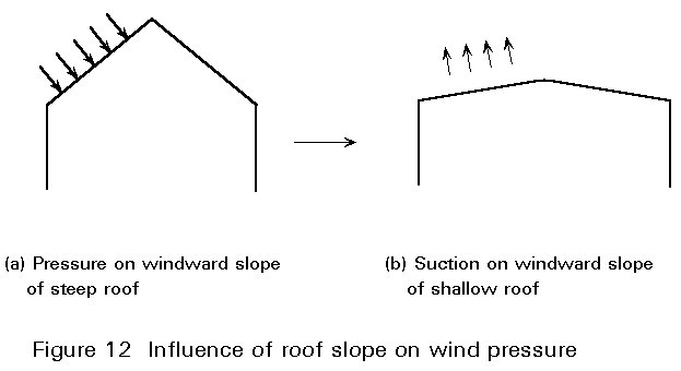
  • roof pitch; this parameter is really a special aspect of structural shape. It is worth noting that roofs with a very shallow pitch may be subject to uplift or suction, whilst steeper roofs - say greater than about 20° - are likely to be subject to a downwards pressure (Figure 12).
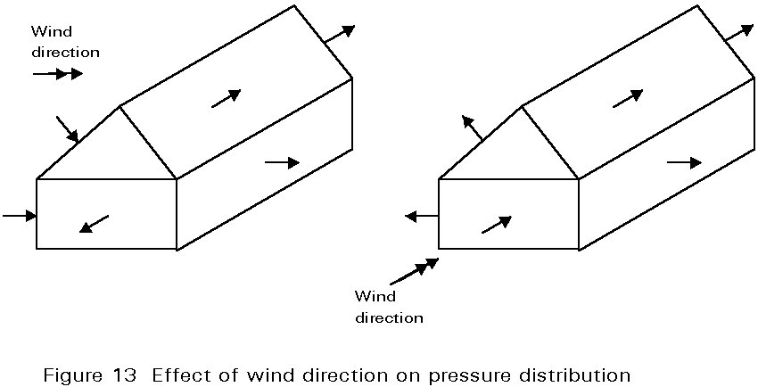
  • wind direction; pressure distributions will change for different wind directions (Figure 13).
  • gust response factor; this factor is used to take into account the reduction of the spatial average of the wind pressure with increasing area due to the non-coincidence of maximum local pressures acting on the external surface of the structure. Thus small parts of a building, such as cladding units and their fixings, must be designed for higher wind pressures than the whole structure. The gust response factor is related to an equivalent height, which corresponds approximately to the centroid of the net wind force on a structure.
Tabulated procedures enable the above parameters to be accounted for firstly in calculating the design wind speed, and secondly in translating that wind speed into a system of forces on the structure. These equivalent static forces can then be used in the analysis and resistance design of the structure, as a whole. However, certain additional features of wind should also be taken into account:
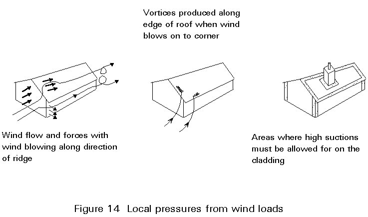
  • local pressures, particularly at corners and around obstructions in an otherwise 'smooth' surface, can be significantly higher than the general level (Figure 14). High local pressures particularly affect cladding and fixing details, but can also be a consideration for structural elements in these areas.
  • structures sensitive to wind should be given a more sophisticated treatment. It might involve wind tunnel testing and include the influence of surrounding buildings. Structures which might need to be treated in this way include high-rise buildings, long or slender bridges, masts and towers.
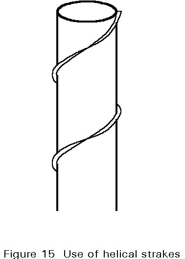
  • aerodynamic instability may be a consideration for certain types of structure or component, for example chimneys and masts. Vortex shedding can normally be avoided by the use of strakes (Figure 15). Galloping may be a problem in cables.

3.7 Snow Loads

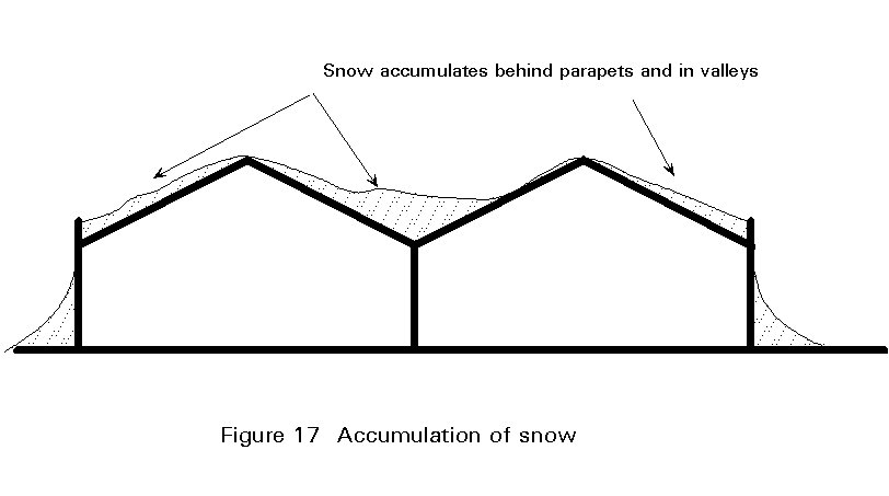
Loads due to snow have traditionally been treated by specifying a single load intensity, with possible reductions for steep roof slopes. This approach takes no account of such aspects as the increased snowfall at higher altitudes or of locally higher loads due to drifting. Cases of complete or partial collapse due to snow load are not unknown [5]. A more rational approach is to use a snow map giving basic snow load intensities for a specified altitude and return period similar to the treatment for basic wind speeds (Figure 16). Corrections for different altitudes or design life can then be applied as shown in Table 2. At present the European snow map is provisional and further work is under way to acquire more data.
Allowance for different roof configurations can be dealt with by means of a shape coefficient. It provides for conditions such as accumulations of snow behind parapets, in valleys and at abrupt changes of roof height (Figure 17). In addition to snow falling in calm conditions, it may be necessary to consider the effects of wind. Wind may cause a redistribution of snow, and in some cases its partial removal from roofs. Any changes in snow distribution on roofs due to excessive heat loss through part of the roof or snow clearing operations should be accounted for if such loading patterns are critical. Eurocode 1 [1] does not cover additional wind loads due to the presence of snow or the accretion of ice, nor loads in areas where snow is present throughout the year.

3.8 Wave Loading

For offshore structures in deep and hostile waters, wave loads can be particularly severe. The loads arise due to movement of water associated with wave action. These movements can be described mathematically to relate forces to physical wave characteristics such as height and wavelength.
The treatment is therefore similar to wind loads in that these physical characteristics are predicted and corresponding forces on the particular structural arrangement then calculated. These calculation procedures are, however, very complicated and must realistically be performed on a computer.

3.9 Temperature Effects

Exposed structures such as bridges may be subject to significant temperature variation which must be taken into account in the design. If it is not provided for in terms of allowing for expansion, significant forces may develop and must be included in the design calculations. In addition, differential temperatures, e.g. between the concrete deck and steel girders of a composite bridge, can induce a stress distribution which must be considered by the designer.

3.10 Retained Material

Structures for retaining and containing material (granular or liquid) will be subject to a lateral pressure. For liquids it is simply the hydrostatic pressure. For granular material a similar approach can be adopted, but with a reduction in pressure depending on the ability of the material to maintain a stable slope - this is the Rankine approach. Ponding of water on flat roofs should be avoided by ensuring adequate falls (1:60 or more) to gutters.

3.11 Seismic Loads

In some parts of the world earthquakes are a very important design consideration. Seismic actions on structures are due to strong ground motion. They are a function of the ground motion itself and of the dynamic characteristics of the structure.
Strong ground motion can be measured by one of its parameters, the maximum ground acceleration being the parameter most usually adopted for engineering purposes. These parameters are expressed on a probabilistic basis, i.e. they are associated with a certain probability of occurrence or to a return period, in conjunction with the life period of the structure [3].

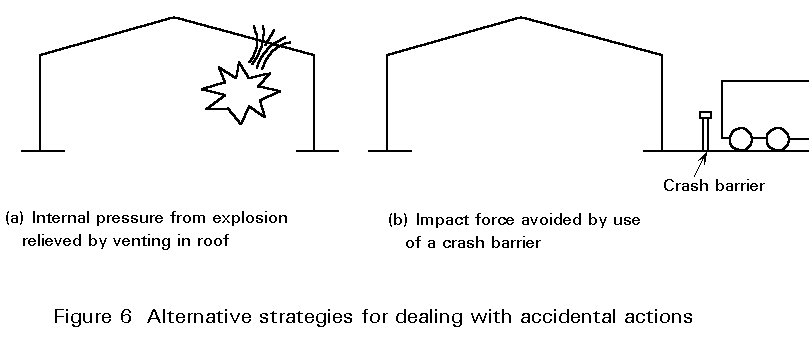
3.12 Accidental Loads

Accidental actions may occur as a result of accidental situations. The situations include fire, impact or explosion. It is very difficult to quantify these effects. In many cases it may be preferable to avoid the problem, for instance by providing crash barriers to avoid collision from vehicles or roof vents to dissipate pressures from explosions.
Where structures such as crash barriers for vehicles and crowds must be designed for 'impact' the loading is treated as an equivalent static load.

4. CONCLUDING SUMMARY

  • There are many sources of structural loads, notably dead loads, those due to the use of the structure and environmental effects such as wind, earthquake, snow and temperature. The loads must be quantified for the purpose of structural design. Dead loads can be calculated. Imposed loads can only be related to type of use through observation on other similar structures. Environmental loads are based on a statistical treatment of recorded data.
  • Calculated or prescribed values of loads are factored to provide an adequate margin of safety. The nature, as well as the magnitude, of the loads must be recognised, particularly in terms of dynamic and fatigue behaviour.

5. REFERENCES

[1] Eurocode 1: Basis of Design and Actions on Structures, CEN (in preparation).
[2] Eurocode 3: Design of Steel Structures: ENV 1993-1-1: Part 1.1, General principles and rules for buildings, CEN, 1992.
[3] Eurocode 8: Structures in Seismic Regions - Design, CEN (in preparation).
[4] Floor Loadings in Office Buildings - the Results of a Survey, BRE Current Paper 3/71, Building Research Establishment, Watford, 1971.
[5] Design Practice and Snow Loading - Lessons from a Roof Collapse, The Structural Engineer, Vol 64A, No 3, 1986.

6. ADDITIONAL READING

  1. Monograph on Planning and Design of Tall Buildings, Volume CL, Tall Building Criteria and Loading, American Society of Civil Engineers, 1980.
  2. Civil Engineer's Handbook, Butterworths, London, 1974.
  3. Bridge Aerodynamics Conference, Institute of Civil Engineers, Thomas Telford, London, 1981.
  4. On Methods of Load Calculation, CIB Report No 9, Rotterdam, 1967.
  5. BRE The Designer's Guide to Wind Loading of Building Structures
Part 1 Butterworths, 1985
Part 2, Butterworths, 1990.
Loaded Areas                          a
[kN/m2]
Category A


Category B


Category C


Category D
- general
- stairs
- balconies

- general
- stairs, balconies

- with fixed seats
- other

- general
2,0
3,0
4,0

3,0
4,0

4,0
5,0

5,0
Table 1 Imposed loads on floors in buildings

Snow load so [kN/m2]
Altitude [m]
Zone0200400600
10,400,490,700,95
20,800,981,401,89
31,201,472,092,84
41,601,972,793,78
52,002,462,494,73
Table 2 Snow loads for zones given in Figure 16so = 0,412z 
where:
A is the altitude of the site above mean sea level [m]
z is a constant, depending on the snow load zone.

Lecture 1B.2.2: Limit State Design Philosophy and Partial Safety Factors


ESDEP WG 1B
STEEL CONSTRUCTION:
INTRODUCTION TO DESIGN

Lecture 1B.2.2: Limit State Design

Philosophy and Partial Safety Factors

OBJECTIVE/SCOPE

To explain the philosophy of limit state design in the context of Eurocode 3: Design of Steel Structures. To provide information on partial safety factors for loads and resistance and to consider how the particular values can be justified.

RELATED LECTURES

Lecture 1B.1: Process of Design
Lecture 1B.3: Background to Loadings
Lecture 1B.8: Learning from Failures
Lecture 2.4: Steel Grades and Qualities
Lecture 2.5: Selection of Steel Quality

SUMMARY

The need for structural idealisations is explained in the context of developing quantitative analysis and design procedures. Alternative ways of introducing safety margins are discussed and the role of design regulations is introduced. The philosophy of limit state design is explained and appropriate values for partial safety factors for loads and strength are discussed. A glossary of terms is included.

1. INTRODUCTION

The fundamental objectives of structural design are to provide a structure which is safe and serviceable to use, economical to build and maintain, and which satisfactorily performs its intended function. All design rules, whatever the philosophy, aim to assist the designer to fulfil these basic requirements. Early design was highly empirical. It was initially based largely upon previous experience, and inevitably involved a considerable number of failures. Physical testing approaches were subsequently developed as a means of proving innovative designs. The first approaches to design based upon calculation methods used elastic theory. They have been used almost exclusively as the basis for quantitative structural design until quite recently. Limit state design is now superseding the previous elastic permissible stress approaches and forms the basis for Eurocode 3 [1] which is concerned with the design of steel structures. In the following sections the principles of limit state design are explained and their implementation within design codes, in particular Eurocode 3, is described.

2. PRINCIPLES OF LIMIT STATE DESIGN

The procedures of limit state design encourage the engineer to examine conditions which may be considered as failure - referred to as limit states. These conditions are classified into ultimate and serviceability limit states. Within each of these classifications, various aspects of the behaviour of the steel structure may need to be checked.
Ultimate limit states concern safety, such as load-carrying resistance and equilibrium, when the structure reaches the point where it is substantially unsafe for its intended purpose. The designer checks to ensure that the maximum resistance of a structure (or element of a structure) is adequate to sustain the maximum actions (loads or deformations) that will be imposed upon it with a reasonable margin of safety. For steelwork design the aspects which must be checked are notably resistance (including yielding, buckling, and transformation into a mechanism) and stability against overturning (Figure 1). In some cases it will also be necessary to consider other possible failure modes such as fracture due to material fatigue and brittle fracture.
Serviceability limit states concern those states at which the structure, although standing, starts to behave in an unsatisfactory fashion due to, say, excessive deformations or vibration (Figure 2). Thus the designer would check to ensure that the structure will fulfil its function satisfactorily when subject to its service, or working, loads.
These aspects of behaviour may need to be checked under different conditions. Eurocode 3 for instance defines three design situations, corresponding to normal use of the structure, transient situations, for example during construction or repair, and accidental situations. Different actions, i.e. various load combinations and other effects such as temperature or settlement, may also need to be considered (Figure 3).
Despite the apparently large number of cases which should be considered, in many cases it will be sufficient to design on the basis of resistance and stability and then to check that the deflection limit will not be exceeded. Other limit states will clearly not apply or may be shown not to govern the design by means of quite simple calculation.
At its most basic level limit state design simply provides a framework within which explicit and separate consideration is given to a number of distinct performance requirements. It need not necessarily imply the automatic use of statistical and probabilistic concepts, partial safety factors, etc., nor of plastic design, ultimate load design, etc. Rather it is a formal procedure which recognises the inherent variability of loads, materials, construction practices, approximations made in design, etc., and attempts to take these into account in such a way that the probability of the structure becoming unfit for use is suitably small. The concept of variability is important because the steelwork designer must accept that, in performing his design calculations, he is using quantities which are not absolutely fixed or deterministic. Examples include values for loadings and the yield stress of steel which, although much less variable than the properties of some other structural materials, is known to exhibit a certain scatter (Figure 4). Account must be taken of these variations in order to ensure that the effects of loading do not exceed the resistance of the structure to collapse. This approach is represented schematically in Figure 5 which shows hypothetical frequency distribution curves for the effect of loads on a structural element and its strength or resistance. Where the two curves overlap, shown by the shaded area, the effect of the loads is greater than the resistance of the element, and the element will fail.
Proper consideration of each of the limits eliminates the inconsistencies of attempting to control deflection by limiting stresses or of avoiding yield at working load by modifying the design basis (formula, mathematical model, etc.) for an ultimate resistance determination.
The procedure of limit state design can therefore be summarised as follows:
  • define relevant limit states at which the structural behaviour is to be checked.
  • for each limit state determine appropriate actions to be considered.
  • using appropriate structural models for design, and taking account of the inevitable variability of parameters such as material properties and geometrical data, verify that none of the relevant limit states is exceeded.

3. ACTIONS

An action on a structure may be a force or an imposed deformation, such as that due to temperature or settlement. Actions are referred to as direct and indirect actions respectively in Eurocode 3.
Actions may be permanent, e.g. self-weight of the structure and permanent fixtures and finishes, variable, e.g. imposed, wind and snow loads, or accidental, e.g. explosions and impact (Figure 6). For earthquake actions, see Lectures 17  and Eurocode 8 [2]. Eurocode 1 [3] represents these by the symbols G, Q and A respectively, together with a subscript - k or d to denote characteristic or design load values respectively. An action may also be classified as fixed or free depending upon whether or not it acts in a fixed position relative to the structure.

3.1 Characteristic Values of Actions (Gk, Qk and Ak)

The actual loadings applied to a structure can seldom be defined with precision; liquid retaining structures may provide exceptions. To design a structure for the maximum combination of loads which could conceivably be applied would in many instances be unreasonable. A more realistic approach is to design the structure for 'characteristic loads', i.e. those which are deemed to have just acceptable probability of not being exceeded during the lifetime of the structure. The term 'characteristic load' normally refers to a load of such magnitude that statistically only a small probability, referred to as the fractile, exists of it being exceeded.
Imposed loadings are open to considerable variability and idealisation, typically being related to the type of occupancy and represented as a uniform load intensity (Figure 7). Dead loads are less variable although there is evidence that variations arising in execution and errors can be substantial, particularly in the case of in-situ concrete and finishes such as tarmac surfacing on road bridges.
Loadings due to snow, wind, etc. are highly variable. Considerable statistical data on their incidence have been collated. Consequently it is possible to predict with some degree of certainty the risk that these environmental loads will exceed a specified severity for a particular location.

3.2 Design Values of Actions (Gd, Qd and Ad)

The design value of an action is its characteristic value multiplied by an appropriate partial safety factor. The actual values of the partial factors to be used depend upon the design situation (normal, transient or accidental), the limit state and the particular combination of actions being considered. Corresponding values for the design effects of actions, such as internal forces and moments, stresses and deflections, are determined from the design values of the actions, geometrical data and material properties.

4. MATERIAL PROPERTIES

Variability of loading is only one aspect of uncertainty relating to structural behaviour. Another important one is the variability of the structural material which is reflected in variations in strength of the components of the structure. Again, the variability is formally accounted for by applying appropriate partial safety factors to characteristic values. For structural steel, the most important property in this context is the yield strength.

4.1 Characteristic Values of Material Properties

The characteristic yield strength is normally defined as that value below which only a small proportion of all values would be expected to fall. Theoretically this can only be calculated from reliable statistical data. In the case of steel, for practical reasons a nominal value, corresponding typically to the specified minimum yield strength, is generally used as the characteristic value for structural design purposes. This is the case in Eurocode 3 which tabulates nominal values of yield strength for different grades of steel.

4.2 Design Values of Material Properties

The design value for the strength of steel is defined as the characteristic value divided by the appropriate partial safety factor. Other material properties, notably modulus of elasticity, shear modulus, Poisson's ratio, coefficient of linear thermal expansion and density, are much less variable than strength and their design values are typically quoted as deterministic.
In addition to the quantified values used directly in structural design, certain other material properties are normally specified to ensure the validity of the design procedures included within codified rules. For instance Eurocode 3 stipulates minimum requirements for the ratio of ultimate to yield strength, elongation at failure and ultimate strain if plastic analysis is to be used [1].

5. GEOMETRICAL DATA

Geometrical data are generally represented by their nominal values. They are the values to be used for design purposes. The variability, for instance in cross-section dimensions, is accounted for in partial safety factors applied elsewhere. Other imperfections such as lack of verticality, lack of straightness, lack of fit and unavoidable minor eccentricities present in practical connections should be allowed for. They may influence the global structural analysis, the analysis of the bracing system, or the design of individual structural elements and are generally accounted for in the design rules themselves.

6. PARTIAL SAFETY FACTORS

Instead of the traditional single factor of safety used in permissible stress design, limit state design provides for a number of partial safety factors to relate the characteristic values of loads and strength to design values. ISO Standard 2394 [4] suggests the use of seven partial safety factors but these are often combined to simplify design procedures. This is the case in the Eurocodes [1,3] which include factors for actions and resistance. Further details are given in the Appendix.
In principle, the magnitude of a partial safety factor should be related to the degree of uncertainty or variability of a particular quantity (action or material property) determined statistically. In practice, whilst this appears to be the case, the actual values of the partial safety factors used incorporate significant elements of the global safety factor and do not represent a rigorous probabilistic treatment of the uncertainties [5-8].
In essence the characteristic actions (Fk) are multiplied by the partial safety factors on loads (gF) to obtain the design loads (Fd), that is:
Fd = gf Fk
The effects of the application of the design loads to the structure, i.e. bending moment, shear force, etc. are termed the 'design effects' Ed.
The design resistance Rd is obtained by dividing the characteristic strengths Rk by the partial safety factors on material gM, modified as appropriate to take account of other considerations such as buckling. For a satisfactory design the design resistance should be greater than the 'design effect'.

7. ULTIMATE LIMIT STATE

The following conditions may need to be verified under appropriate design actions:
a. Ed,dst £ Ed,stb
where Ed,dst and Ed,stb are the design effects of destabilising and stabilising actions respectively. This is the ultimate limit state of static equilibrium.
b. Ed £ Rd
where Ed and Rd are the internal action and resistance respectively. In this context it may be necessary to check several aspects of an element's resistance. These aspects might include the resistance of the cross-section (as a check on local buckling and yielding), and resistance to various forms of buckling (such as overall buckling in compression, lateral-torsional buckling and shear buckling of webs), as well as a check that the structure does not transform into a mechanism.
c. no part of the structure becomes unstable due to second order effects.
d. the limit state of rupture is not induced by fatigue.

8. SERVICEABILITY LIMIT STATE

The serviceability limit state is generally concerned with ensuring that deflections are not excessive under normal conditions of use. In some cases it may also be necessary to ensure that the structure is not subject to excessive vibrations. Cases where this is particularly important include structures exposed to significant dynamic forces or those accommodating sensitive equipment. Both deflection and vibration are associated with the stiffness rather than strength of the structure.

8.1 Deflections

At the serviceability limit state, the calculated deflection of a member or of a structure is seldom meaningful in itself since the design assumptions are rarely realised because, for example:
  • the actual load may be quite unlike the assumed design load.
  • beams are seldom "simply supported" or "fixed" and in reality a beam is usually in some intermediate condition.
  • composite action may occur.
The calculated deflection is, however, valuable as an index of the stiffness of a member or structure, i.e. to assess whether adequate provision is made in relation to the limit state of deflection or local damage. For this purpose, sophisticated analytical methods are seldom justified. Whatever methods are adopted to assess the resistance and stability of a member or structure, calculations of deflection should relate to the structure of the elastic state. Thus, when analysis to check compliance with the strength limit is based on rigid-elastic or elastic-plastic concepts, the structural behaviour in the elastic phase must also be considered.
Calculated deflections should be compared with specified maximum values, which will depend upon circumstances. Eurocode 3 [1] for instance tabulates limiting vertical deflections for beams in six categories as follows:
  • roofs generally.
  • roofs frequently carrying personnel other than for maintenance.
  • floors generally.
  • floors and roofs supporting plaster or other brittle finish or non-flexible partitions.
  • floors supporting columns (unless the deflection has been included in the global analysis for the ultimate limit state).
  • situations in which the deflection can impair the appearance of the building.
In determining the deflection it may be necessary to consider the effects of precamber, permanent loads and variable loads separately. The design should also consider the implications of the deflection values calculated. For roofs, for instance, regardless of the limits specified in design rules, there is a clear need to maintain a minimum slope for run-off. More stringent limits may need therefore to be considered for nearly flat roof structures.

8.2 Dynamic Effects

The dynamic effects to be considered at the serviceability limit state are vibration caused by machinery and self-induced vibrations, e.g. vortex shedding. Resonance can be avoided by ensuring that the natural frequencies of the structure (or any part of it) are sufficiently different from those of the excitation source. The oscillation and vibration of structures on which the public can walk should be limited to avoid significant discomfort to the users. This situation can be checked by performing a dynamic analysis and limiting the lowest natural frequency of the floor. Eurocode 3 recommends a lower limit of 3 cycles per second for floors over which people walk regularly, with a more severe limit of 5 cycles per second for floors used for dancing or jumping, such as gymnasia or dance halls [1]. An alternative method is to ensure adequate stiffness by limiting deflections to appropriate values.

9. STRUCTURAL DESIGN MODELS

No structural theory, whether elastic or plastic, can predict the load-carrying resistance of a structure in all circumstances and for all types of construction. The design of individual members and connections entails the use of an appropriate structural theory to check the mode of failure; sometimes alternative types of failure may need to be checked and these may require different types of analysis. For example, bending failure by general yielding can only occur when the plastic moment is attained; however bending failure is only possible if failure does not occur at a lower load level by either local or overall buckling.
Serviceability limit states are concerned with the performance of the structure under service loading conditions. The behaviour should therefore be checked on the basis of an elastic analysis, regardless of the model used for the ultimate limit state design.

10. CONCLUDING SUMMARY

  • Limit state design procedures require formal examination of different conditions which might lead to collapse or inadequate performance.
  • The effect of various actions is compared with the corresponding resistance of the structure under defined failure criteria (limit states).
  • The most important failure critera are the ultimate limit state (collapse) and the serviceability limit state of deflection.
  • In checking each limit state, appropriate design models must be used to provide an accurate model of the corresponding structural behaviour.
  • Separate partial safety factors are introduced for loading and material. These factors are variable quantities and the precise values to be used in design reflect the degree of variability in the action or resistance to be factored.
  • Different combinations of action may also require different values of safety factor.
  • This flexible approach helps provide a more consistent level of safety compared with other design approaches.

11. GLOSSARY

A limit state is a condition beyond which the structure no longer satisfies the design performance requirements.
The ultimate limit state is a state associated with collapse and denotes inability to sustain increased load.
The serviceability limit state is a state beyond which specified service requirements are no longer met. It denotes loss of utility and/or a requirement for remedial action.
Characteristic loads (Gk, Qk, Ak) are those loads which have an acceptably small probability of not being exceeded during the lifetime of the structure.
The characteristic strength (fy) of a material is the specified strength below which not more than a small percentage (typically 5%) of the results of tests may be expected to fall.
Partial safety factors (g Gg Qg M) are the factors applied to the characteristic loads, strengths, and properties of materials to take account of the probability of the loads being exceeded and the assessed design strength not being reached.
The design (or factored) load (Gd, Qd, Ad) is the characteristic load multiplied by the relevant partial safety factor.
The design strength is the characteristic strength divided by the appropriate partial safety factor for the material.

12. REFERENCES

[1] Eurocode 3: "Design of Steel Structures" ENV 1993-1-1: Part 1.1: General Rules and Rules for Buildings, CEN, 1992.
[2] Eurocode 8: "Structures in Seismic Regions-Design", CEN (in preparation).
[3] Eurocode 1: "Basis of Design and Actions on Structures" CEN (in preparation).
[4] ISO 2394, General Principles for the Verification of the Safety of Structures, International Standards Organisation, 1973.
[5] Rationalisation of Safety and Serviceability Factors in Structural Codes, CIRIA Report 63, London, 1972.
[6] Allen, D. E., "Limit States Design - A Probabilistic Study", Canadian Journal of Civil Engineers, March 1975.
[7] Augusti, G., Baratta, A., and Casciati, F., "Probabilistic Methods in Structural Engineering", Chapman and Hall, London 1984.
[8] Armer, G. S. T., and Mayne, J. R, "Modern Structural Design Codes - The Case for a More Rational Format", CIB Journal Building Research and Practice, Vol. 14, No. 4, pp 212-217, 1986.

13. ADDITIONAL READING

1. Pugsley, A., "The Safety of Structures", Edward Arnold, London 1966.
2. Thoft-Christensen, P., and Baker, M. J., "Structural Reliability Theory and its Application", Springer-Verlag, 1982.
3. "The Steel Skeleton", Cambridge University Press, Vol 1 1960, Vol II 1965.
4. Blockley, D., "The Nature of Structural Design and Safety", Ellis Horwood, Chichester, 1980.
5. Fukumoto, Y., Itoh, Y. and Kubo, M., "Strength Variation of Laterally Unsupported Steel Beams", ASCE, Vol 106, ST1, 1980.
6. ISO 8930: General Principles on Reliability of Structures - List of Equivalent Terms, 1987.
APPENDIX - PARTIAL SAFETY FACTORSPartial safety factors for actionsEurocodes 1 and 3 define three partial safety factors as follows:
gG permanent actions
gQ variable actions
gA accidental actions
Two values are specified for gG. These are gG,sup and gG,inf representing 'upper' and 'lower' values respectively. Where permanent actions have an adverse effect on the design condition under consideration, the partial safety factor should be the upper value. However, where the effect of a permanent action is favourable (for instance in the case of loads applied to a cantilever when considering the design of the adjacent span), the lower value for the partial safety factor should be used, see Figure 8.
The treatment of load combinations is quite sophisticated, and involves the definition of 'representative' values, determined by applying a further factor to the design loads, depending upon the particular combination considered. However, simplified procedures are generally permitted. They are outlined below. Note that the values of partial safety factors are indicative only. Although they are specified in Eurocode 3, their precise value may be adjusted by individual countries for use within the country.
Load combinations for the ultimate limit stateEither, all permanent loads plus one variable load, all factored, i.e:
S gG Gki + gQ Qk1
where gG and gQ are taken as 1,35 and 1,5 respectively,
or, all permanent loads plus all variable loads, all factored, i.e:
S gG Gki + S gQ Qki
where gG and gQ are both taken as 1,35.
These values recognise the reduced probability of more than one variable load existing simultaneously. For instance, although a structure may on occasions be subject to its maximum wind load, it is much less likely that it will be exposed to a combination of maximum wind and imposed loads.
Load combinations for the serviceability limit stateEither, all permanent loads plus one variable load are considered. In each case the partial safety factor is unity, i.e. the loads are unfactored characteristic values:
S Gki + Qk1
or, all permanent loads (partial safety factor unity) plus all variable loads (with a partial safety factor of 0,9), i.e:
S Gki + 0,9 S Qki
Where simplified compliance rules are provided for serviceability, there is no need to perform detailed calculations with different load combinations.
Partial safety factors for materialAlternative partial safety factors for material are specified as follows:
gM0 = 1,1 for consideration of resistance of Class 1, 2 or 3 cross-section.
gM2 = 1,1 for consideration of resistance of Class 4 cross-section and resistance to buckling.
gM2 = 1,25 for resistance consideration of cross-section at holes

Lecture 1B.2.1: Design Philosophies


ESDEP WG 1B
STEEL CONSTRUCTION:
INTRODUCTION TO DESIGN

Lecture 1B.2.1: Design Philosophies

OBJECTIVE/SCOPE:

To explain the objectives of structural design and the uncertainties which affect it; to outline how different priorities might influence the design, and to describe different approaches to quantifying the design process.

RELATED LECTURES:

Lecture 1B.1: Process of Design
Lecture 1B.3: Background to Loadings
Lecture 1B.8: Learning from Failures
Lecture 2.4: Steel Grades and Qualities
Lecture 2.5: Selection of Steel Quality

SUMMARY:

The fundamental objectives of structural design are discussed. The uncertainties associated with designing structures in terms of loading and material properties are considered. The development of structural design methods for strength and resistance is reviewed briefly and the importance of achieving structural stability is explained. Other design considerations such as deflections, vibration, force resistance and fatigue are discussed. Matters of construction and maintenance are included. The importance of considering these aspects and others, such as accommodating services and cladding costs, in developing an efficient design is emphasised. The responsibilities of the designer and the need for effective communication are considered.

1. INTRODUCTION

The precise objectives of structural design vary from one project to another. In all cases, the avoidance of collapse is an important - if not the most important - requirement and an adequate factor of safety must be provided. In this context, the structure must be designed in order to fulfil both strength and stability requirements. These concepts are illustrated in Figure 1 in which a long thin rod is subject to tension (Figure 1a) and compression (Figure 1b). In the case of tension, the load resistance of the rod is governed by strength, that is the ability of the material to carry load without rupturing. The rod can only carry this load in compression if it remains stable, i.e. it does not deform significantly in a direction perpendicular to the line of action of the applied load. The stiffness of the structure is yet another important characteristic, concerned with resistance to deformation rather than collapse. This is particulary important in the case of beams whose deflection under a particular load is related to their stiffness (Figure 1c). Large deformations are not necessarily associated with collapse, and some brittle materials, such as glass, may rupture with little prior deformation. Other considerations may also need to be included in the design process. They include: quantifiable behaviour such as deformation, fatigue, fire resistance and dynamic behaviour; considerations such as corrosion and service accommodation which may influence both detail and overall concept, but in a more qualitative way; and appearance, which is largely a subjective judgement. In addition considerations of economy are likely to be a significant influence on the great majority of structural designs. In this context questions of speed and ease of construction, maintenance and running costs, as well as basic building costs, are all relevant. The relative importance of each of these aspects will vary depending on circumstances.
The approach to structural design is dealt with in Lecture 1B.1, which describes how the designer might begin to accommodate so many different requirements, many of which will exert conflicting pressures. In this lecture the focus is on how a satisfactory structural design can be achieved through a rational analysis of various aspects of the structure's performance. It is worth emphasising that the process of structural design can be considered as two groups of highly interrelated stages. The first group is concerned with defining the overall structural form - the type of structure, e.g. rigid frame or load bearing walls, the arrangement of structural elements (typically in terms of a structural grid), and the type of structural elements and material to be used, e.g. steel beams, columns and composite floor slabs. A high degree of creativity is required. The synthesis of a solution is developed on the basis of a broad understanding of a wide range of topics. The topics include structural and material behaviour, as well as a feel for the detailed implications of design decisions made at this stage - for instance recognising how deep a beam may need to be for a particular purpose. Formalised procedures are of little use at this stage. A satisfactory solution depends more on the creative ability of the designer.
The later stages are concerned with the more detailed sizing of structural components and the connections between them. By now the problem has become clearly defined and the process can become more formalised. In the case of steelwork the process generally involves selecting an appropriate standard section size, although in some circumstances the designer may wish to use a non-standard cross-section which, for execution, would then need to be made up, typically by welding plates or standard sections together into plate girders or trusses.
Design regulations are largely concerned with this stage of detailed element design. Their intention is to help ensure that buildings are designed and constructed to be safe and fit for purpose. Such design legislation can vary considerably in approach. It may be based simply on performance specification, giving the designer great flexibility as to how a satisfactory solution is achieved. An early example of this is the building laws published by King Hummarabi of Babylon in about 2200BC. They are preserved as a cuneiform inscription on a clay tablet and include such provisions as 'If a builder builds a house for a man and does not make its construction firm and if the house which he has built collapses and causes the death of the owner of the house, then that builder shall be put to death. If it causes the death of the son of the owner of the house, then a son of the builder shall be put to death. If it causes the death of a slave of the owner of the house, then the builder shall give the owner a slave of equal value'. The danger, and at the same time the attraction, of such an approach is that it depends heavily on the ability of the designer. Formal constraints, based on current wisdom, are not included and the engineer has the freedom to justify the design in any way.
The other extreme is a highly prescriptive set of design rules providing 'recipes' for satisfactory solutions. Since these can incorporate the results of previous experience gained over many years, supplemented by more recent research work they might appear to be more secure. However, such an approach cannot be applied to the conceptual stages of design and there are many cases where actual circumstances faced by the designer differ somewhat from those envisaged in the rules. There is also a psychological danger that such design rules assume an 'absolute' validity and a blind faith in the results of using the rules may be adopted.
Clearly there is a role for both the above approaches. Perhaps the best approach would be achieved by specifying satisfactory performance criteria to minimise the possibility of collapse or any other type of 'failure'. Engineers should then be given the freedom to achieve the criteria in a variety of ways, but also be provided with the benefit of available data to be used if appropriate. Perhaps the most important aspect is the attitude of the engineer which should be based on simple 'common sense' and include a healthy element of scepticism of the design rules themselves.

2. UNCERTAINTIES IN STRUCTURAL DESIGN

Simply quantifying the design process, using sophisticated analytical techniques and employing powerful computers does not eliminate the uncertainties associated with structural design, although it may reduce some of them.
These uncertainties include the following:
  • loading.
  • constitutive laws of the material.
  • structural modelling.
  • structural imperfections.
Loading is discussed in more detail in Lecture 1B.3. Although it is possible to quantify loads on a structure, it is important to recognise that in most cases these represent little more than an estimate of the likely maximum load intensity to which a structure will be exposed. Some loads, such as the self weight of the structure, may appear to be more easily defined than others, such as wind loads or gravity waves on offshore structures. However, there is a significant degree of uncertainty associated with all loads and this should always be recognised.
Constitutive laws are typically based on the results of tests carried out on small specimens. For convenience, the mathematical representation of the behaviour, for instance in the form of a stress-strain curve, is considered in a simplified form for the purpose of structural design. In the case of steel the normal representation is linear elastic behaviour up to the yield point with plastic behaviour at higher strains (Figure 2). Although this representation provides a reasonable measure of the performance of the material, it is clearly not absolutely precise. Furthermore, any material will show a natural variability - two different samples taken from the same batch will typically fail at different stresses when tested. Compared with other materials, steel is remarkably consistent in this respect, but nevertheless variations exist and represent a further source of uncertainty.
Methods of analysing structural behaviour have advanced significantly in recent years, particularly as a result of developments in computing. Despite this, structural analysis is always based on some idealisation of the real behaviour. In some cases, such as isolated beams supported on simple bearings, the idealisation may be quite accurate. In other circumstances, however, the difference between the model and the real structure may be quite significant. One example of this is the truss which is typically assumed to have pinned joints, although the joints may in fact be quite rigid and some members may be continuous. The assumption that loadings are applied only at joint positions may be unrealistic. Whilst these simplifications may be adequate in modelling overall performance the implications, at least with regard to secondary effects, must be recognised.
Yet another source of uncertainty results from structural imperfections which are of two types: geometrical, i.e. out of straightness or lack of fit, and mechanical, i.e. residual stresses due to fabrication procedures or inhomogenities in the material properties. It is not possible to manufacture steel sections to absolute dimensions - wear on machinery and inevitable variations in the manufacturing process will lead to small variations which must be recognised. In the same way, although steel construction is carried out to much tighter tolerances than for most other structural materials, some variations (for instance in the alignment of individual members) will occur (Figure 3).
In adopting a quantified approach to structural design, all these uncertainties must be recognised, and taken into account. They are allowed for by the following means:
  • specifying load levels which, based on previous experience, represent the worst conditions which might relate to a particular structural type.
  • specifying a sampling procedure, a test plan and limits on material properties.
  • specifying limits or tolerances for both manufacture and execution.
  • using appropriate methods of analysis, whilst recognising the difference between real and idealised behaviour.
These measures do not eliminate the uncertainties but simply help to control them within defined bounds.

3. DESIGNING TO AVOID COLLAPSE

3.1 Historical Background

Structural design is not something which is new. Ever since man started building - dwellings, places of worship, bridges - some design philosophy has been followed, albeit often unconsciously. For many centuries the basis of design was simply to copy previous "designs". Where "new developments" or modifications were introduced, trial and error techniques were all that was available. As a result many structures were built, or partially built only to collapse or perform inadequately. Yet these failures did have a positive value in that they contributed to the fund of knowledge about what is workable and what is not.
This unscientific approach persisted for many centuries. Indeed it still forms part of the design approach adopted today. Rules of thumb and empirical design recommendations are frequently used, and these are largely based on previous experience. Nor is structural engineering today totally free of failures, despite the apparent sophistication of design methods and the power of computers. The dramatic box girder bridge collapses in the early 1970s were a grim reminder of what can happen if new developments are too far ahead of existing experience.
The emergence of new materials, notably cast and wrought iron, required a new approach and the development of more scientific methods. The new approach included testing, both of samples of the material and proof testing of structural components and assemblies. New concepts too were sometimes justified in this way, for instance in the case of the Forth Rail Bridge.
The first moves to rationalise structural design in a quantitative way came at the beginning of the 19th century with the development of elastic analysis. This type of analysis allowed engineers to determine the effect (on individual structural components) of forces applied to a complete structure.
Testing of materials provided information concerning strength and, in the case of iron and steel, other characteristics such as the elastic limit. Of course there were often great variations in the values measured, as indeed there are even today with some materials. In order to ensure a safe design, a lower bound on the test results - a value below which experimental data did not fall - was normally adopted as the 'strength'. Recognising some of the uncertainties associated with design methods based on calculation, stresses under maximum working load conditions were limited to a value equal to the elastic limit divided by a factor of safety. This factor of safety was specified in an apparently arbitrary fashion with values of 4 or 5 being quite typical.
This approach provided the basis of almost all structural design calculations until quite recently, and for some applications is still used today. As understanding of material behaviour has increased and safety factors have become more rationalised, so design strengths have changed. Changes in construction practice, and the development of new, higher strength materials, have necessitated detailed changes in design rules, particularly with regard to buckling behaviour. However the basic approach remained unchanged until quite recently when certain limitations in classical allowable-stress design became apparent. The limitations can be summarised as follows:
i. there is no recognition of the different levels of uncertainty associated with different types of load.
ii. different types of structure may have significantly different factors of safety in terms of collapse, and these differences do not appear in any quantifiable form.
iii. there is no recognition of the ductility and post-yield reserve of strength characteristic of structural steelwork.
The last of these limitations was overcome by the work of Baker [1] and his colleagues in the 1930s when plastic design was developed. This method was based upon ensuring a global factor of safety against collapse, allowing localised 'failure' with a redistribution of bending stresses. A comparison of elastic and plastic design is given by Beal [2].
In recognition of the disadvantages of the allowable stress design method, an alternative approach, known as limit state design has been adopted. Limit state design procedures have now become well established for most structural types and materials. The approach recognises the inevitable variability and uncertainty in quantifying structural performance, including the uncertainties of material characteristics and loading levels. Ideally, each uncertainty is typically treated in a similar manner using statistical techniques to identify typical or characteristic values and the degree of variation to be expected from this norm [3]. It is then possible to derive partial safety factors, one for each aspect of design uncertainty, which are consistent. Thus different load types, for instance, have different factors applied to them. The structure is then examined for a variety of limit states. In that case the structure is designed to fail under factored loading conditions, giving a clearer picture of the margins of safety than was previously the case with allowable stress design.

3.2 Stability

Inadequate strength is not the only cause of collapse. In particular the designer must ensure adequate stability, both of the complete structure (a function of the overall structural form) and of each part of it (dependent on individual member proportions and materials). The latter is generally dealt with by modifying the material strength to account for individual conditions. Overall stability is very much more difficult to quantify and must be carefully considered at the earliest stage of structural design. In this sense structural stability can be defined by the conditions that a structure will neither collapse (completely or partially) due to minor changes, for instance in its form, condition or normal loading, nor be unduly sensitive to accidental actions. Some examples are shown in Figure 4.
In designing for stability the positioning of the main load-bearing elements should provide a clearly defined path for transmitting loads, including wind and seismic actions to the foundations. In considering wind loads on buildings it is important to provide bracing in two orthogonal vertical planes, distributed in such a way as to avoid undue torsional effects, and to recognise the role of the floor structure in transmitting wind loads to these braced areas (Figure 5). The bracing can be provided in a variety of ways, for instance by cross-bracing elements or rigid frame action.
Consideration of accidental actions, such as explosions or impact, is more difficult, but the principle is to limit the extent of any damage caused. Limitation of damage can be achieved by designing for very high loads (not generally appropriate) or providing multiple load paths. Design requires consideration of local damage rendering individual elements of the structure ineffective, and ensuring the remaining structure is able to carry the new distribution of loads, albeit at a lower factor of safety. Alternative strategies are to provide for dissipation of accidental actions, for instance by venting explosions, and to protect the structure, for instance by installing bollards to prevent vehicle impact on columns (Figure 6).
Structural stability must of course be ensured when alterations are to be carried out to existing structures. In all cases stability during execution must be very carefully considered.

3.3 Robustness

In many ways robustness is associated with stability. Construction forms which fulfil the primary function of accommodating normal loading conditions - which are highly idealised for design purposes - may not perform a secondary function when the structure is subject to real loading conditions. For instance the floor of a building is normally expected to transmit wind loads in the horizontal plane to the braced positions. Transmission of wind loads can only be achieved if there is adequate connection between the floor and other parts of the structure and building fabric, and the floor itself is of a suitable form of construction.

4. OTHER DESIGN OBJECTIVES

Although design against collapse is a principal consideration for the structural engineer, there are many other aspects of performance which must be considered. None of these aspects can be quantified and only certain ones will normally apply. However, for a successful solution, the designer must decide which considerations can be ignored, what the most important criteria are in developing the design, and which can be checked simply to ensure satisfactory performance.

4.1 Deformation

The deflection characteristics of a structure are concerned with stiffness rather than strength. Excessive deflections may cause a number of undesirable effects. They include damage to finishes, (particularly where brittle materials such as glass or plaster are used), ponding of water on flat roofs (which can lead to leaks and even collapse in extreme cases), visual alarm to users and, in extreme cases, changes in the structural behaviour which are sufficient to cause collapse. Perhaps the most common example of deflection effects occurs in columns, which are designed for largely compressive loads but may become subject to significant bending effects when the column deforms in a horizontal plane - the so called P-delta effect.
The normal approach in design is to check that calculated deflections do not exceed allowable levels, which are dependent upon structural type and finishes used. For instance, deflection limits for roof structures are not normally as severe as those for floor structures. In performing these checks it is important to recognise that the total deflection dmax consists of various components, as shown in Figure 7, namely:
dmax = d1 + d2 - d0
where d1 is the deflection due to permanent loads
d2 is the deflection due to variable loads
d0 is the precamber (if any) of the beam in the unloaded state.
In controlling deflections it is often necessary to consider both dmax and d2, with more severe limits applying in the latter case.
Although the calculated deflections do not necessarily provide an accurate prediction of likely values, they do give a measure of the stiffness of the structure. They are therefore a reasonable guide to structural performance in this respect. With the trend towards longer spans and higher strength materials, design for deflection has become more important in recent years. In many cases this consideration dictates the size of structural elements rather than their resistance. In the case of certain structures, deflection control is of paramount importance. Examples include structures supporting overhead cranes and those housing sensitive equipment. Design for deflection is likely to be the critical condition in such cases.

4.2 Vibration

The vibration characteristics of a structure are, like deflection behaviour, dependent upon stiffness rather than strength. The design principle is to adopt a solution for which the natural frequency of vibration is sufficiently different from any source of excitation, such as machines, to avoid resonance. Longer spans, lighter structures and a reduction in the mass and stiffness of partitions and cladding have all contributed to a general lowering of the natural frequencies for building structures. Cases of human discomfort have been recorded and Eurocode 3 [4] now requires a minimum natural frequency of 3 cycles per second for floors in normal use and 5 cycles per second for dance floors.
Wind excited oscillations may also need to be considered for unusually flexible structures such as very slender, tall buildings, long-span bridges, large roofs, and unusually flexible elements such as light tie rods. These flexible structures should be investigated under dynamic wind loads for vibrations both in-plane and normal to the wind direction, and be examined for gust and vortex induced vibrations. The dynamic characteristics of the structure may be the principal design criterion in such cases.

4.3 Fire Resistance

The provision for safety in the event of fire is dealt with in Group 4B. It is a common requirement that structural integrity is maintained for a specified period to allow building occupants to escape and fire-fighting to be carried out without the danger of structural collapse. For steel structures alternative design strategies can be adopted to achieve this requirement. The traditional approach has been to complete the structural design 'cold' and to provide some form of insulation to the steelwork. This approach can give an expensive solution and alternative methods have now been developed, allowing reductions, and in some cases complete elimination, of fire protection. In order to implement these alternatives in an effective manner, it is important that, at an early stage in the design process, the structural design considers how the fire resistance of the steelwork is to be achieved. Adopting a design solution which may be relatively inefficient in terms of the weight of steel for normal conditions may be more than offset by savings in fire protection (Figure 8).
Buildings close to a site boundary may require special consideration to prevent an outbreak of fire spreading to adjacent sites due to structural collapse. Again quantitative design procedures have been developed for such circumstances [5].

4.4 Fatigue

Where structures, or individual structural elements, are subject to significant fluctuations in stress, fatigue failure can occur after a number of loading cycles at stress levels well below the normal static resistance. The principal factors affecting fatigue behaviour are the range of stresses experienced, the number of cycles of loading and the environment. Structures which need particular consideration in this respect are crane gantry girders, road and rail bridges, and structures subject to repeated cycles from vibrating machinery or wind-induced oscillations. Design guidance is included in Eurocode 3 [4].

4.5 Execution

One of the principal advantages of steelwork is the speed with which execution can proceed. In order to maximise this advantage it may be necessary to adopt a structurally less efficient solution, for instance by using the same profile for all members in a floor construction, even though some floor beams are less highly loaded than others (Figure 9). Temporary propping should be avoided as must late changes in detail which might affect fabrication.
It is important that the structure is not considered in isolation, but rather treated as one part of the complete construction, along with services, cladding and finishes. By adopting a co-ordinated approach to the design, integrating the parts and eliminating or reducing wet trades, speed of execution of the project as a whole can be maximised. A good example of this is the two-way continuous grillage system used for the BMW Headquarters at Bracknell and other projects [6].
The installation of services can have significant implications for speed, cost and detail of construction. In buildings with major service requirements, the cost of the services can be considerably greater than the cost of the structure. In such circumstances it may well be better to sacrifice structural efficiency for ease of accommodating the services. The design of the total floor zone including finishes, structure, fire protection and services also has implications for other aspects of the building construction. The greater the depth of floor construction, the greater the overall height of the building and hence the quantity of external cladding required. In many commercial developments very sophisticated and expensive cladding systems are used. Savings in cladding systems may more than offset the use of shallower, but less efficient, floor construction. Where there is strict planning control of overall building height, it may even be possible to accommodate additional storeys in this way.

4.6 Maintenance

All structures should be inspected and maintained on a regular basis, although some conditions are likely to be more demanding in this respect. For instance, steelwork within a dry, heated interior environment should not suffer from corrosion, whilst a bridge structure in a coastal area will need rigorous maintenance schedules. Some structural forms are easier to maintain than others, and where exposure conditions are severe, ease of inspection and maintenance should be an important criterion. Principal objectives in this context are the avoidance of inaccessible parts, dirt and moisture traps, and the use of rolled or tubular individual sections in preference to truss-like assemblies composed of smaller sections.

5. DESIGN RESPONSIBILITIES

One engineer should be responsible for ensuring that the design and details of all components are compatible and comply with the overall design requirements. This responsibility is most important when different designers or organisations are responsible for individual parts of the structure, such as foundations, superstructure and cladding. It should include an appraisal of the working drawings and other documents to establish, inter alia, that requirements for stability have been incorporated in all elements, and that they can be met during the execution stage.
Effective communication both within the design team and between the designer and constructor before and during execution is essential. Good communication will help to avoid potential design conflicts, for instance when services have to penetrate the structure, and also to promote safe completion of the structure in accordance with the drawings and specification. The constructor may also require information concerning results of site surveys and soil investigations, design loadings, load resistance of members, limits on positions of construction joints, and lifting positions on members to be erected as single pieces. A statement accompanied by sketches detailing any special requirements should be prepared when necessary, e.g. for any unusual design or for any particularly sensitive aspects of the structure or construction. This statement should be made available to the contractor for appropriate action regarding temporary works and execution procedures.
The designer should be made aware of the proposed construction methods, erection procedures, use of plant, and temporary works. The execution programme and sequence of erection should be agreed between the designer and constructor.
Full and effective communication between all parties involved will help not only to promote safe and efficient execution but may also improve design concepts and details. Design should not be seen as an end in itself, but rather as an important part of any construction project.

6. CONCLUDING SUMMARY

  • There are very many uncertainties associated with structural design. However powerful the tools available, the engineer should always recognise that the design model is no more than an idealisation and simplification of the real condition.
  • A quantified approach to structural design can take different forms with a view to providing a framework for satisfactory solutions. The application of design rules should be tempered with common sense and understanding.
  • Structural design must consider many aspects of both performance and cost. The most efficient structural solution may not result in the most efficient solution overall if other interdependent aspects of the construction are not considered in a co-ordinated fashion.

7. REFERENCES

[1] Baker, J.F., and Heyman, J. "Plastic Design of Frames 1: Fundamentals", Cambridge University Press, 1969.
[2] Beal, A.N. "What's wrong with load factor design?", Proc. ICE, Vol. 66, 1979.
[3] Armer, G.S.T., and Mayne, J.R. "Modern Structural Design Codes - The case for a more rational format", CIB Journal Building Research and Practice, Vol. 14, No. 4, pp. 212-217, 1986.
[4] Eurocode 3 "Design of Steel Structures" ENV1992-1-1: Part 1: General Rules and Rules for Buildings, CEN, 1992.
[5] Newman, G.J. "The behaviour of portal frames in boundary conditions", Steel Construction Institute.
[6] Brett, P.R. 'An alternative approach to industrial building", The Structural Engineer, Nov. 1982.